Navigation Strategy of a Shopping Assistant Robot
Webpage to the navigation strategy of the Shopping Assitant Robot based on the project I-RobEka (Supported by the Federal Ministry of Education and Research Germany).Introduction
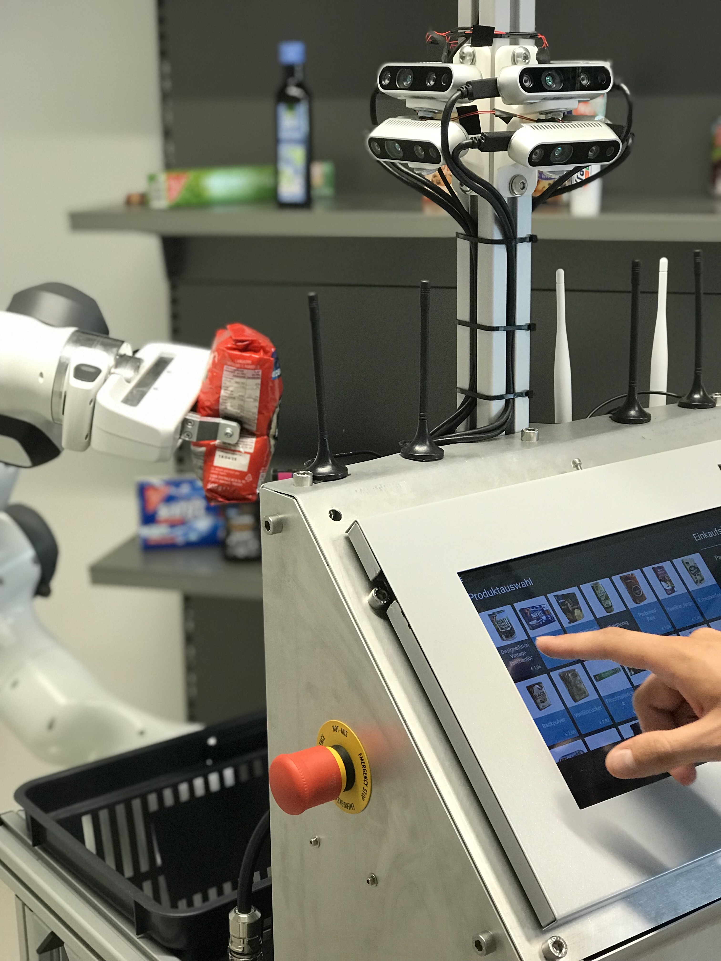
The following material demonstrates the navigation strategy for a mobile shopping assistant robot in a supermarket environment. The purpose of the present system is to support people while shopping in the supermarket. For example, the robot provides product information or their position in the market, works as a guide, or as a shopping cart, which follows a customer. However, a major goal of this development is autonomous shopping: with a list of items, the robot collects them efficiently and bring them to the customer or checkout.
System description
The following picture shows the robot with all sensor and actors:
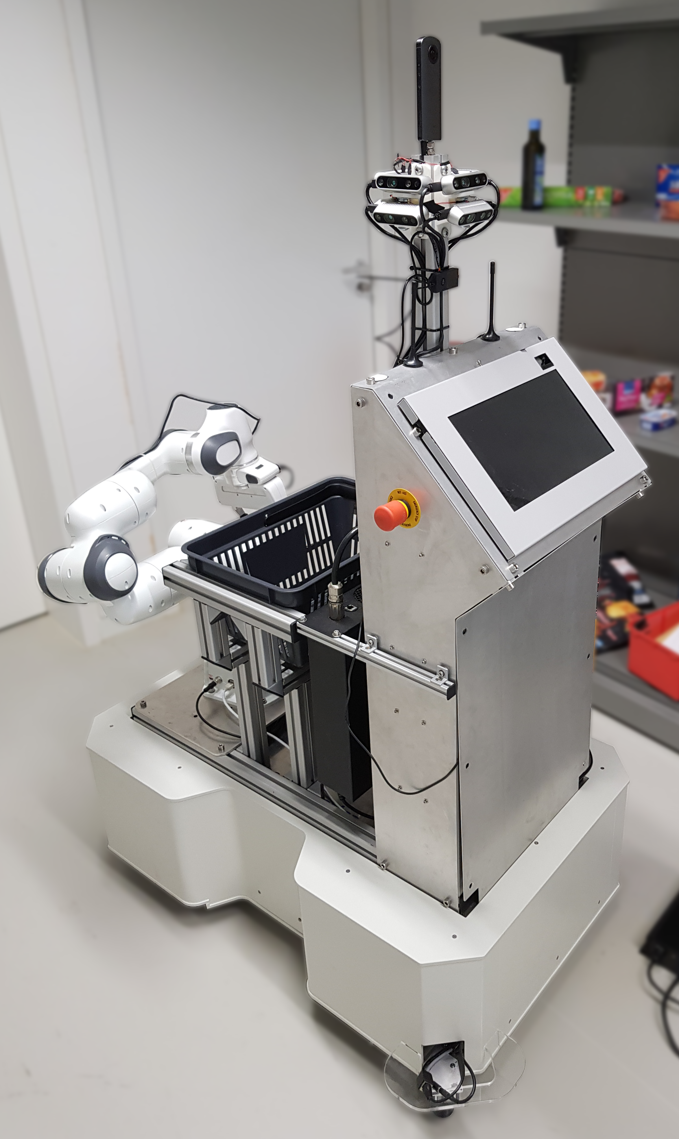
Detailed Sensor-Setup:
- Two 2D laser-scanners (Hokuyo UTM-30LX-EW), which are located on diagonal corners of the case to get a 360$^\circ$ field of view. They are used for localization and collision avoidance. They are mounted very low (6cm over the ground) in order to perceive the bottom panel of the supermarket shelves.
- One inertial measurement unit (IMU MTI-3-8A7G6-DK) located in the center of the robot to improve the wheel odometry based on wheel encoders.
- In total, there are eight RGB-D cameras (Realsense D435), arranged in two horizontal rings of four cameras to allow 360 degree perception and a large vertical field of view.
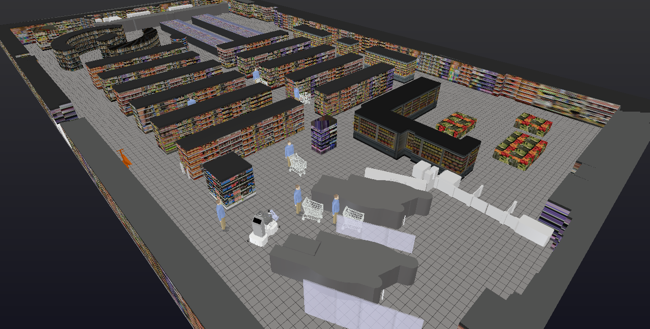
Simulation
In order to develop the navigation strategy independently of the real robot system, we have created a simulation environment. It is based on the simulation software V-Rep (currently under the name CoppeliaSim) in version 3.5.
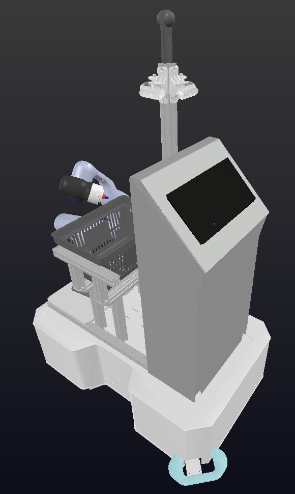
Digital Twin of the real Platform
The robot model based on the real CAD model with all sensors and actuators, and can be seen in the following figure:
Supermarket Environment
To create the 3D model of the simulated supermarket, we evaluated two approaches:
- Using 3D point cloud SLAM
- Creating 3D maps from available 2D floor plans
1. Using 3D point cloud SLAM
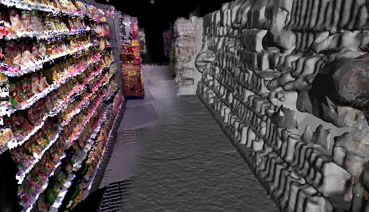
We did a 3D measurement of a real supermarket with a robot that is equipped with the 360 degrees laser scanner to produce a real representation of the market. After getting several 3D scans of different places in the supermarket, we fused these to one map with the ICP registration algorithm and aligned RGB images with the 3D point cloud to obtain a colored point cloud representation of the market. The result of the colored point cloud can be seen in the following video:
Afterward, we created a mesh from the points to use it in the simulation (for visualization, the image contains both - from left to right is going from the point cloud to the mesh (shown in gray tones)):
2. Creating 3D maps from available 2D floor plans
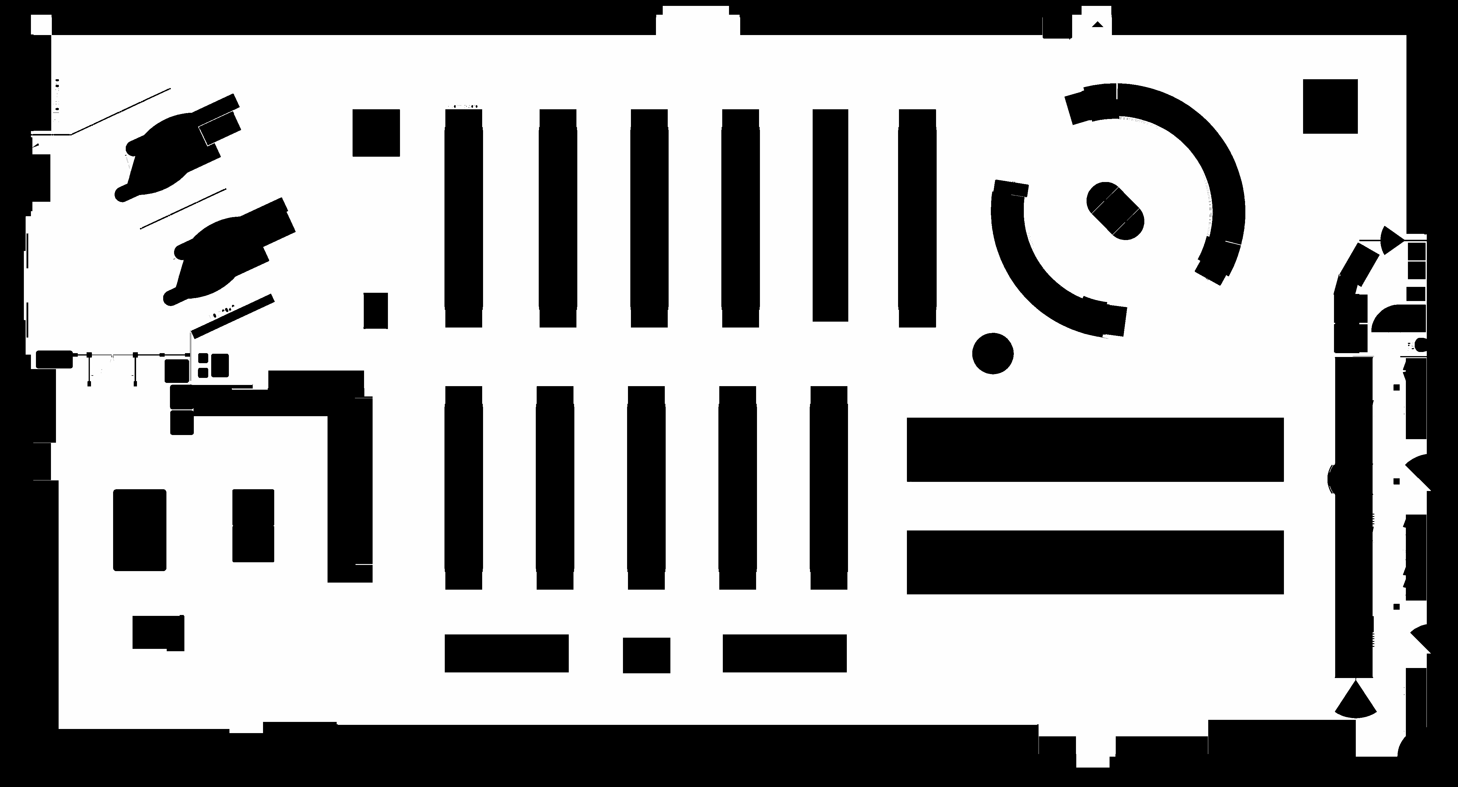
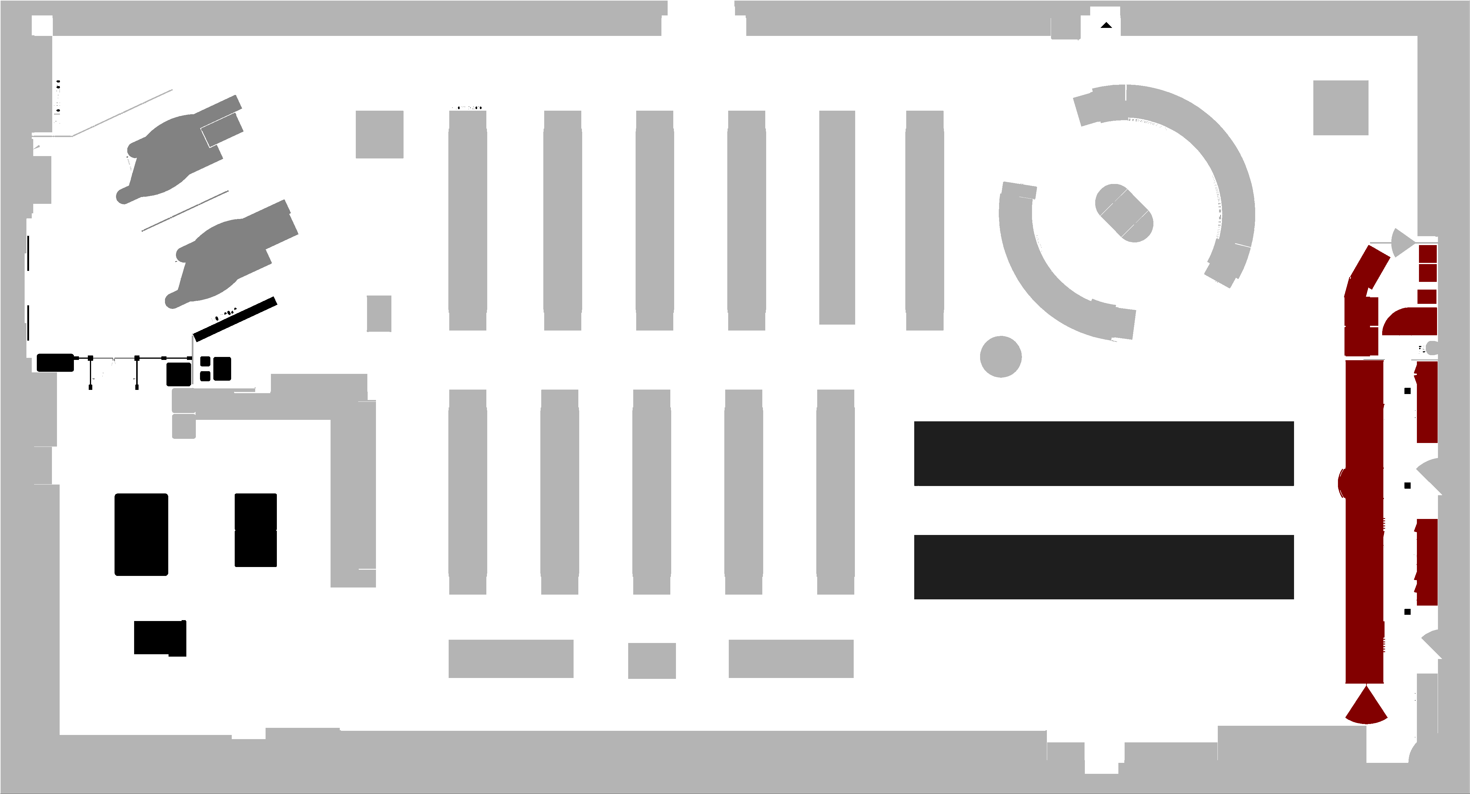
The target shopping assistant robot is developed in cooperation with a supermarket company. Thus, we are in the comfortable position to have floor plans available that also include a layout of the larger furniture (e.g., the shelves). To create a 3D model with primitive geometric objects from the 2D floor plan, we conduct the following steps:
- We use standard image processing tools to transform the floor plan to predefined color code for the different semantic objects and categories (e.g., the floor has the color white, all shelves of a particular type have another color value, and so on). This requires some manual configuration and supervision.
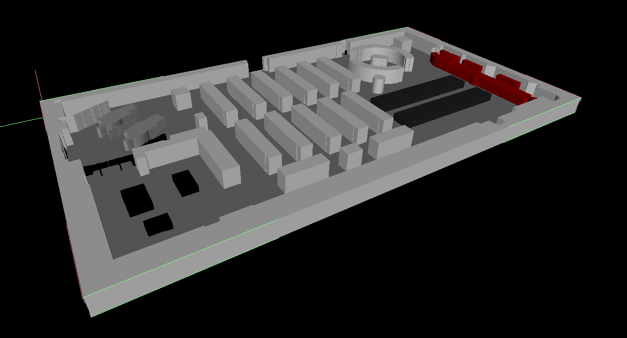
- Based on a script we can create a 3D model automatically from the 2D color-coded image (basically, each area in the 2D image with a specific color becomes a 3D object with the corresponding predefined height).
- Finally, texturing all these primitive geometric objects with supermarket images creates the environment in V-Rep.
- Error correction and loop closure detection in our point-cloud SLAM required some careful human intervention
- The created mesh needs a high effort to smooth some irregularities and reducing the complexity of the surface.
- The high resolution of the created mesh made the simulation very slow and increased the computation time for rendering and sensing.
Navigation
Route Planning
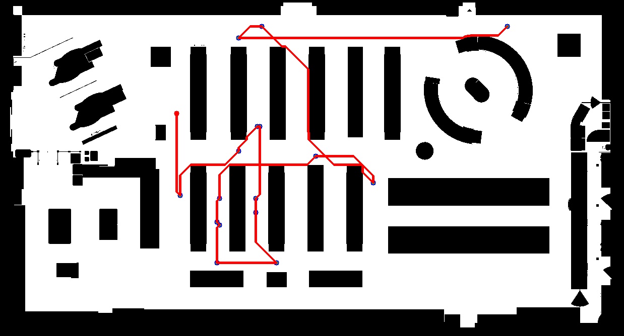
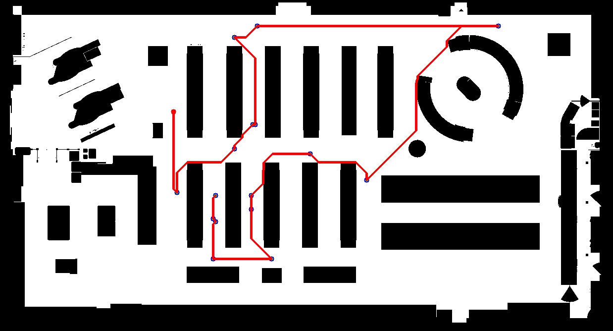
The robot's important task is to plan the most time-efficient and shortest path to collect all selected items. It is done via solving a 'Traveling Salesman Problem' (TSP). There are two possible solutions: approximated or exact. One of the approximated solving can be the nearest neighbor method. It calculates the order by finding the nearest article based on a list of items (locations) and the given floor plan. This greedy algorithm produces only an approximated solution and not necessarily an optimal order of all items. To get an optimal solution of the TSP, we use the CONCORD Solver. The following picture shows the results of planning with 16 items from both the nearest neighbor and the CONCORD solver:
Path and Motion Planning
We calculate the global plan to the next item with an A* planner based on the ordered item list from the TSP solver. It uses the global floorplan as a map. After having our global path from the current position to the next item, we need a planner that reacts to unknown obstacles (static objects which are not in floor plan) and dynamic objects like people. A local planner can realize such behavior - it uses the global plan and adopts it regarding currently seen obstacles. A well suitable planner to incorporate dynamic obstacles is the TEB Planner. It is an online optimization algorithm based on a hypergraph (factor graph) and optimizes towards a minimum execution time. All nodes within the graph are waypoints (sampled from the solution of the global A* planner), and all edges represent the penalization functions (e.g., close to an obstacle The current implementation provides an extension to incorporate dynamic obstacles and adapt the trajectory with the optimization of the factor graph. It enables long term planning and creates a path that avoids any collisions (static or dynamic) efficiently. To use the planner optimally, we have to provide all obstacles individually. The following picture gives an overview and shows three different layers: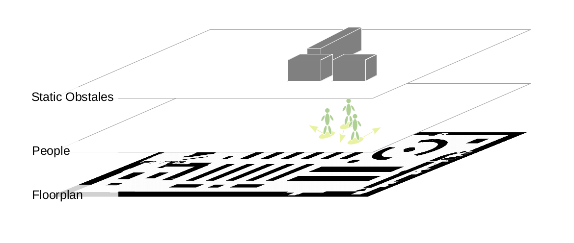
To see how the planning avoids moving people, we provide 3 different scenarios simulation with our digital twin. The videos are showing the simulation environment and the appropriate visualization in RViz.
- One moving person that passes frontal
- One moving person that passes from the side
- Two moving people pass the robot
The robot moves ahead and the person comes frontal to pass the robot. It can be seen that the people detection system recognizes the person and track them (pillars represent the tracked person). From that point, the local TEB planner tries to avoid the trajectory of the person.
While the robot is moving, a person crosses the path from the side. It will be recognized and included in the motion planning.
While the robot is moving, one person passes the robot frontal and one person from the side.
State Control
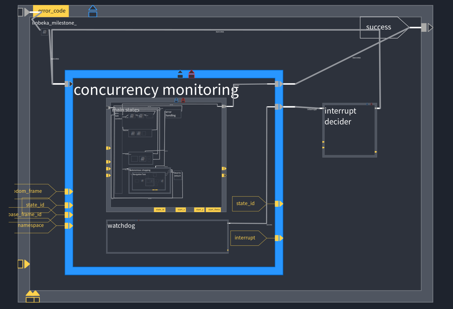
A task (state) control software is necessary to control the order of all tasks and subtasks (e.g., localization, global planning, or reaction on inputs by the customer). We are using RAFCON which is a graphical tool to construct hierarchical tasks and allows real-time intervention and monitoring. All states contain a python script that represents the executed code if the state is active.
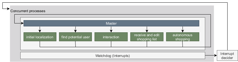
A high-level concept of our state machine can be seen in the following picture:
Our implementation of the statemachine in RAFCON can be seen in the next picture: