The SysTick is used (among other things) for triggering user functions in a constant time interval with a maximum frequency of 100Hz and for controlling the servo. For providing this functionality, the microcontroller's internal timer1 functionality is used. For a complete description of the timer's functionality, see the ATmega644 documentation. In the following, the properties used for implementing the SysTick are described.
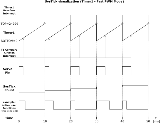
For getting a constant time interval, the timer's overflow interrupt is used, while the timer is set to Fast PWM mode. Fast PWM mode means, that a counter starts at a value BOTTOM and counts until a value TOP. Afterwards, the counter starts again from BOTTOM. Each time, the value TOP is reached, an timer overflow interrupt is triggered. (See figure) For changing into the fast PWM mode used here, the bits WGM11, WGM12, and WGM13 in the registers TCCR1A and TCCR1B have to be set.
As we wish to get an interval of 10ms for the overflow interrupt, we need to set the 16 bit register ICR1 for the TOP value according to the following equation:
![\[ f_\textrm{sys}=\frac{f_\textrm{clk}}{\textrm{prescaler}\cdot(1+\textrm{TOP})} \]](form_0.png)
![\[ \textrm{TOP} = \frac{20 \textrm{MHz}}{8 \cdot 100\textrm{Hz}} -1 = 24999 \]](form_1.png)
As prescaler, a value of 8 is used (CS11 bit of the TCCR1B register) and according to the equation, ICR1H has to be set to 0x61A7. (ICR1H=0x61 and ICR1L=0xA7)
By default, the overflow interrupt is disabled, so the bit TOIE1 has to be set for enabling it. So the complete code is:
As already mentioned, the timer is also used for controlling the servo position. For this functionality, the timer's "Output Compare A Match Interrupt" is used. This interrupt triggers, if the current timer's count reaches the value of the register OCR1. The interrupt is activated by setting the OCIE1A bit of register TIMSK1 (see code above).
The following figure shows a visualization of the timer's functionality including the servo output and an example of possible user functions added to the timer's overflow interrupt. User functions can be added with time_cycle_add.